
Greetings - Cronapressman here.
This blog entry will cover a 'live' fit of the Patented Safezone alarm strip. Incorporated into this fit is the use of the new 'Robust' End Caps, use of the conduit adapter to link to standard UK electrical conduit, and use of the centre channel to run twin wires to an external E.O.L. (E.O.L. - End of line resistor possibly in another strip within the zone monitoring for line faults). The 'Cronapress Single Zone' controller will be used to manage the alarm strip and a key operated reset incorporated into the conduit junction box will be used also to give a visual of how simple this system is to install on small projects. The alarm strip will be mounted to a typical wall that reflects a quality found within older buildings/corridors/factories etc. The fitting tools used will be those typically found within an alarm engineers toolbox. Thus this should result in a valuable guide for both project and alarm engineers to evaluate the work involved before undertaking fitment.
(Alarm cabling may simply exit from the wall and the Robust End Cap plate should cover this adequately if need be. Alternatively this same plate can also mount to a sunken pattress box. I'll cover these on a separate blog entries)
Step 1
Securely fix the Safezone aluminium base extrusion to the wall. Note - Screw fixing holes are pre-drilled at regular intervals along the length of the base but evaluation of the buildings structure must be undertaken and fixings to suit used. Additional holes can easily be drilled and a datum line is molded into the extrusion specifically for this purpose down the centre channel. Obviously, use of a builders spirit level or laser is a must. Note - End Caps will add a further 60mm to each end so allow for this if cutting base to customers overall size requirements.

The 'Robust' end cap base plate tangs can now be inserted into the underside of the extrusion, push up firmly against the aluminium and mark the wall for fixing. Remove, drill, plug, and refit. Repeat at the other end if using identical plates.. Note the additional screw fixing near the end of the base to firmly secure the base extrusion against the irregular surface of the wall.

For our project we are using the conduit adapter so the fixing holes for this can now be marked and drilled. To ensure the End Cap cover fits straight and secure it is best to sit the End Cap cover over the base aluminium before marking the wall. There are 4 holes to secure this conduit adapter to the wall. (2 each end) Depending on the angle of exit of the conduit junction box trunking determines where the box is drilled through to match the wall fixings as the same screws secure both. Note - The End Cap cover will be finally fixed in position later after wiring tests but the 2 x fixing holes should be pre-drilled and plugged now.


Do not at this stage fix this conduit adapter to the wall as cabling will need to be run behind and into the junction box.
Step 3
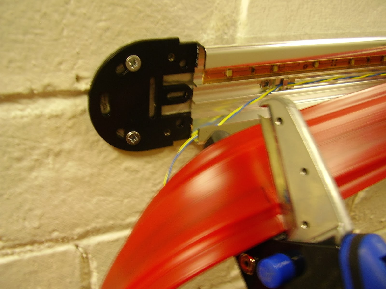
Fit the L.E.D. lighting strip into either the top or bottom channel. The twin wire alarm cable to our remotely positioned E.O.L. is held within the centre channel by means of Self Adhesive Cable Clips. Note - Nothing must protrude higher than the top of the channels or the alarm insert will be compromised and false activations may occur. Take particular notice where cabling runs over fixing screws.

Feeding cabling behind the conduit adapter. (Fixing plugs drilled as above)

Cut the insert to size (match the base in length). Measuring can accurately be done either with tape measure or sitting the insert into bottom of base extrusion and marking the end cuts. The shears available from Cronapress are ideal and give an extremely clean cut and are our recommended way of size adjustment. Alternative a craft knife should give acceptable results but sharp blades are a must.
Step 5.
Wired End Plug now inserted and all wiring neatly fed underneath conduit adapter to the junction box. Adaptor and junction box now fixed in position.

Step 6.
Cable joints. As I mentioned at the beginning of this blog entry we are using typical installation tools and methods. Thus our cable joints will be by closed end crimp. A tech tip that was passed to me by an approved installer was to cut the crimp insulation down to the minimum to allow more available room withing the end cap for cabling. See below how I used this technique in the remote E.O.L. circuit. The wired end can also be seen correctly fitted within the strip with the external shoulder of the moulding seated firmly against the insert edge.

Step 7.
Complete all wiring and test for electrical continuity and sound joints/terminations.
Step 8.
The end cap covers can now be screwed into place.

Security Torx screws are used to help resist tamper on the 'Robust End Cap' . Note -The cover applies pressure to the internal electrical connection so insuring it is firmly fixed is vital.

Step 9.
Fill fixing screw holes with plugs supplied. These can be 'superglued' in place for additional anti tamper.


Done ! Hopefully you have found the 'live' fit informative and a fair representation of what can be achieved on site. If you need any more information on the fitment of our products then contact me at Cronapress.
Tools used.
Electric Hammer Drill, rawlplugs and screws.
Builders level.
Engineers hacksaw for cutting conduit.
Appropriate size screwdrivers.
Cronapress approved - Silverline General Purpose Shears.
Cronapress approved - Silverline Crimping Pliers.
Cronapress approved - Stanley Pin Torx Screwdriver.
Self adhesive cable clips.
Cat 5 Alarm Cable.
Cronapress man signing off until next time.
Remember - If it looks right it will be right ! If it doesn't - you guessed it - it won't !