Translate

Showing posts with label Feel-safe. Show all posts

Monday, 17 February 2014

Fitting Safezone Externally.

Greetings - Cronapress man here - As promised in my previous blog post I said I'd be dealing with the fitment of the Patented Safezone alarm strip externally. Once again instead of doing carefully composed 'mock-up' shots I shall be doing a live fit. The external fit has many similarities with the internal fitting so I'll only cover the differences in detail.           So here goes - Let's do it !                                    
Step 1 The aluminium extrusion should be cut to size, drilled with additional fixing holes if required (pre-drilled holes are provided which you may find useful) and securely attached to the wall or external construction. As I recommend in all cases inspection of the mounting area needs to be undertaken and fixings executed accordingly. Note -Allow for an additional 60mm each end for end caps.

Step 2
Fully insert end cap plate tangs into underside of extrusion, mark drilling holes, remove, drill and insert rawlplugs or similar..


Note the additional fixing screw near the edge in the base extrusion due to the uneven brickwork and also the channel that has been cut in the mortor. This will allow the wiring to sit behind the end cap plate and into a galvanised junction box.


Step 3
Fit the waterproof  L.E.D. into either the upper or lower channel in the aluminium extrusion. At this point it may be wise to test the L.E.D. strip with a temporary 12v battery/power pack as it will be time consuming to replace once the insert is installed and sealed.


Step 4
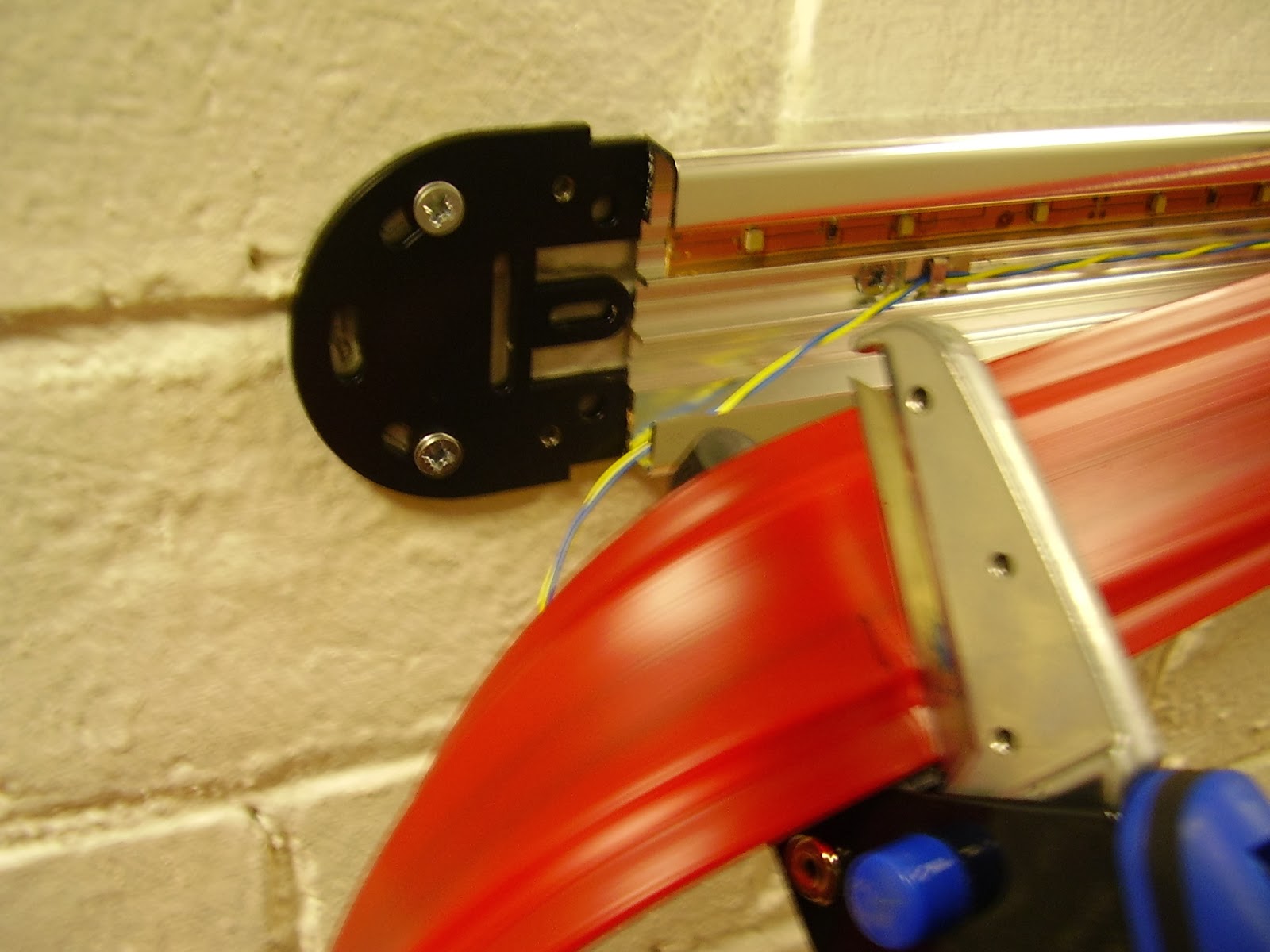
The insert can now be cut to length (if not supplied to size) The multi-purpose shears available from Cronapress are ideal. Information on them can be found on this blog.
NOTE - Cut the insert 10mm oversize each end.
This is very important as the oversize will be used to achieve the weatherproof seal. Sit the insert in the bottom channel and feed the top into place. Take care that the insert does not move when fitting as it will be difficult to re-position once fully home.

Step 5
Once the insert is fully seated into the upper and lower channels of the base extrusion then the wiring plugs are next. On this installation we will be using a Wired End plug and a 1k2 E.O.L. (End of Line) resistor plug.
These have been modified for external fitment and must be specified if needed at time of order. (The shoulder has been removed to allow them to push inside the insert strip.)

With the aid of a small screwdriver gently push the plug inside the insert so that the outer edge is level with the edge of the base extrusion. As mentioned above a 10mm overlap was allowed on the insert size at each end and this is the measurement we push the plug inside. This is of utmost importance so that the electrical contact point is positioned under the pressure point of the end cap cover.

Step 6
 Check for electrical continuity and if test ok then seal with silicone. Use a neutral sealer not a cheap Acetoxic type. We recommend Dow Corning 798. which also has Bacteriostatic qualities which would be of benefit if fitting in wet rooms or showers.


Re-check continuity.


Silicone Tech Talk-
Acetoxi cure.
This is the most commonly used, it is more rigid and the full cure is quick.  On the downside it generally has poor adhesion and leaves much to be desired for in how well it 'sticks' to PVC-U, most other plastics, glass, aluminium and Polycarbonate.  Shrinkage can be acceptable if it does not contain added solvent. 
Since the acetic acid is released during curing, it can attack the underlying substrate material. This can cause corrosion of certain metals and prevent the proper adhesion of the silicone. However, on other materials, the acid can etch the surface slightly and increase the adhesion. Aluminum is one such material. Copper and zinc, however, are corroded by the acid. Thus brass and galvanized steel should not be used with silicones which release acid. Dissimilar metals can form electrolytic couples and corrode severely underneath a covering of acetic acid releasing silicone.
Note the effect that the acid cure may have on the internal copper contact strip within the Safezone insert.
Neutral cure.
Much better adhesive properties for a greater number of materials including PVC-U, most other plastics, glass, aluminium, lead, stone and masonry, and Polycarbonate.  It cures with atmospheric moisture and skins over in about 30 minutes, and leaves a shinier finish.  On the downside it is more expensive and is slower to cure at one to five days depending on thickness, temperature and humidity conditions.
Conclusion:
The benefit of using a good Low Modulus Neutral Cure Silicone can be summed up thus:
It offers high movement accommodation and excellent adhesion to almost all building and glazing materials, without any of the unwanted 'side effects' Acetoxi could possibly cause.

Step 7
Cap off the strip. 

Step 8
The galvanised 22mm conduit junction box has been drilled with a small hole to allow water drainage. Several times I have seen water collect in external trunking and ultimately lead to component failure. Failure will not occur in this instance due to the robust Cronapress sealing techniques but none the less water trapped in electrical conduits is definitely not a good thing and getting in the habit of reducing risk should be encouraged.

Step 9
Connection to the alarm cabling will be made with the same closed end connector crimps that were used in our internal fitting blog page. These will need additional weather protection as follows-
1)Cut the large opening part of the insulator from the crimp. 
2)Crimp the appropriate wires together 
3)Cover with Glue lined Heat shrink End Caps and apply hot air. Job done when tight and glue begins leaching from ends.


Step 10
Cover plate fitted and power on. (Just in time, it's raining again !)


Done ! Hopefully you have found the external 'live' fit informative and a fair representation of what can be achieved on site. If you need any more information on the fitment of our products then contact me at Cronapress.

Tools used.
Electric Hammer Drill, rawlplugs and screws.
Builders level.
Engineers hacksaw for cutting conduit.
Appropriate size screwdrivers.
Cronapress approved - Silverline General Purpose Shears.
Cronapress approved - Silverline Crimping Pliers.
Cronapress approved - Stanley Pin Torx Screwdriver.
Dow Corning 798 Silicone Sealer.
Cat 5 Alarm Cable.

Below - Special components used on this installation.
1) Waterproof LED
2) External fitment wiring plugs.
3) Modified Crimp Connectors - To allow heat shrink coverage.
4) Glue Lined Heat Shrink End Caps.


Cronapress man signing off until next time.
Remember - If it looks right it will be right ! If it doesn't - you guessed it - it won't !

and below is an poor example of external fitting....Now which do you think your customer would prefer?


Friday, 10 January 2014

Fitting Safezone inc 'Robust' end caps and conduit adapter.


Greetings - Cronapressman here.

This blog entry will cover a 'live' fit of the Patented Safezone alarm strip. Incorporated into this fit is the use of the new 'Robust' End Caps, use of the conduit adapter to link to standard UK electrical conduit, and use of the centre channel to run twin wires to an external E.O.L. (E.O.L. - End of line resistor possibly in another strip within the zone monitoring for line faults). The 'Cronapress Single Zone' controller will be used to manage the alarm strip and a key operated reset incorporated into the conduit junction box will be used also to give a visual of how simple this system is to install on small projects. The alarm strip will be mounted to a typical wall that reflects a quality found within older buildings/corridors/factories etc. The fitting tools used will be those typically found within an alarm engineers toolbox. Thus this should result in a valuable guide for both project and alarm engineers to evaluate the work involved before undertaking fitment.
(Alarm cabling may simply exit from the wall and the Robust End Cap plate should cover this adequately if need be. Alternatively this same plate can also mount to a sunken pattress box. I'll cover these on a separate blog entries)

Step 1
Securely fix the Safezone aluminium base extrusion to the wall. Note - Screw fixing holes are pre-drilled at regular intervals along the length of the base but evaluation of the buildings structure must be undertaken and fixings to suit used. Additional holes can easily be drilled and a datum line is molded into the extrusion specifically for this purpose down the centre channel. Obviously, use of a builders spirit level or laser is a must. Note - End Caps will add a further 60mm to each end so allow for this if cutting base to customers overall size requirements.

Step 2
The 'Robust' end cap base plate tangs can now be inserted into the underside of the extrusion, push up firmly against the aluminium and mark the wall for fixing. Remove, drill, plug, and refit. Repeat at the other end if using identical plates.. Note the additional screw fixing near the end of the base to firmly secure the base extrusion against the irregular surface of the wall.


For our project we are using the conduit adapter so the fixing holes for this can now be marked and drilled. To ensure the End Cap cover fits straight and secure it is best to sit the End Cap cover over the base aluminium before marking the wall. There are 4 holes to secure this conduit adapter to the wall. (2 each end) Depending on the angle of exit of the conduit junction box  trunking determines where the box is drilled through to match the wall fixings as the same screws secure both. Note - The End Cap cover will be finally fixed in position later after wiring tests but the 2 x fixing holes should be pre-drilled and plugged now.


Do not at this stage fix this conduit adapter to the wall as cabling will need to be run behind and into the junction box.

Step 3
Fit the L.E.D. lighting strip into either the top or bottom channel. The twin wire alarm cable to our remotely positioned E.O.L. is held within the centre channel by means of Self Adhesive Cable Clips. Note - Nothing must protrude higher than the top of the channels or the alarm insert will be compromised and false activations may occur. Take particular notice where cabling runs over fixing screws.

Step 3a
Feeding cabling behind the conduit adapter. (Fixing plugs drilled as above)

Step 4.
Cut the insert to size (match the base in length). Measuring can accurately be done either with tape measure or sitting the insert into bottom of base extrusion and marking the end cuts. The shears available from Cronapress are ideal and give an extremely clean cut and are our recommended way of size adjustment. Alternative a craft knife should give acceptable results but sharp blades are a must.


Step 5.
Wired End Plug now inserted and all wiring neatly fed underneath conduit adapter to the junction box. Adaptor and junction box now fixed in position.


Step 6.
Cable joints. As I mentioned at the beginning of this blog entry we are using typical installation tools and methods. Thus our cable joints will be by closed end crimp. A tech tip that was passed to me by an approved installer was to cut the crimp insulation down to the minimum to allow more available room withing the end cap for cabling. See below how I used this technique in the remote E.O.L. circuit. The wired end can also be seen correctly fitted within the strip with the external shoulder of the moulding seated firmly against the insert edge.


Step 7.
Complete all wiring and test for electrical continuity and sound joints/terminations.

Step 8.
The end cap covers can now be screwed into place.


Security Torx screws are used to help resist tamper on the 'Robust End Cap' . Note -The cover applies pressure to the internal electrical connection so insuring it is firmly fixed is vital.


Step 9.
Fill fixing screw holes with plugs supplied. These can be 'superglued' in place for additional anti tamper.


Done ! Hopefully you have found the 'live' fit informative and a fair representation of what can be achieved on site. If you need any more information on the fitment of our products then contact me at Cronapress.

Tools used.
Electric Hammer Drill, rawlplugs and screws.
Builders level.
Engineers hacksaw for cutting conduit.
Appropriate size screwdrivers.
Cronapress approved - Silverline General Purpose Shears.
Cronapress approved - Silverline Crimping Pliers.
Cronapress approved - Stanley Pin Torx Screwdriver.
Self adhesive cable clips.
Cat 5 Alarm Cable.


Cronapress man signing off until next time.
Remember - If it looks right it will be right ! If it doesn't - you guessed it - it won't !

Monday, 11 February 2013

Tools of the Trade No1


Cronapressman here - I'm down in the workshop today and I thought I'd just take a few minutes out to show you our recommended cutting tool for the Feelsafe/Safezone insert. (In fact it works pretty good on the 'B' and 'CB' insert too.)
Measure and then mark accurately the cutting point, position the snips at 90degree to the insert and voila a quick snip and the jobs done !
Clean cut - accurate too !
Remember my motto ? -  If it looks right it will be right !   If it doesn't - you guessed it - it won't !


So ! What you waiting for ? Get it touch with me at Cronapress and order the right too for the job.
Don't forget - Keep checking the Cronapress Blogspot for more 'Top Tips' too....
Cronapressman - a.k.a - Edward Scissorhands !!!!!!!!! Snip - Snip - Snip.......

Thursday, 6 December 2012

Safe-zone End Cap Good Practice


Greetings, Cronapressman here - Blogging a few tips on good fitment practice of the Safe-zone End Caps.

Pre-fitment  - To achieve successful electrical continuity through the alarm strip the base rail must first have been securely fixed with appropriate fixings (dependent on wall structure) and the Safe-zone insert must have been trimmed accurately and neatly.
Remember that the insert needs to be cut 1-2 mm shorter than the base rail at each end. I find it best to fit the insert from one end and cut to size when within 50 mm of the opposite end.


Let's take a moment to study the Safe-zone End Cap above -
1) 3 x fixing slots to insure sound wall fitment.
2) 2 x Protruding tangs to insure correct position of connector tongue within the insert by locating under the base extrusion.
3) Rebate to accept sealing silicone if requirement to weatherproof.
4) Cover cap fixing pins (not visible) can be super-glued (Cyanoacrylate) to resist un-authorised removal.

Let's do it -
No 1) - Push the Safe-zone End Cap connector tongue fully home inside insert. Double check protruding tangs are under base.
No 2) - Mark 3 slot positions on wall.
No 3) - Drill wall with appropriate masonry drill and insert masonry plugs.
No 4) - Replace Safe-zone End Cap and fix to wall. Pushing firmly into insert as fixing screws are tightened.
No 5) - Test for electrical continuity.
No 6) - Cover cap to be push fit when alarm has passed testing.
NOTE - Further removal and replacing of cover cap will compromise the ability of the fixing pins to maintain a sound hold. The cover cap is designed to aid the electrical connections by applying a slight downwards pressure.

Remember - If it looks right it will be right !   If it doesn't - you guessed it - it won't !


Keep checking the Cronapress blogspot and Cronapress website for more news and tips.

Sunday, 2 December 2012

The advantage of using 1.2kW resistor on Affray/ Panic Strips

Greetings, 'Cronapress Ken' here presenting -  


Technical and R&D Dept. - Bulletin No1

Why should a press strip profile use a 1.2kW resistor rather than a 10kW?

Although terminating the profile with 1.2kW increases the current and power drawn from the supply, there is an advantage gained if the system is used in the real world where interference is present. If the connecting cable between the profile and the sensing electronics is in ducting where other electrical cables are present then the proximity of these can generate interference signals. Cables carrying high frequencies can be troublesome as  can cables carrying  power at mains frequency when switching transients occur. Radio interference is also another source of interference.

In all cases, magnetic and electric screening will reduce the interference but, unfortunately, it may not be be possible and certainly will be prohibitively expensive. So what can be done about it?

The effect of interference can be represented in simple terms by a voltage source and an impedance representing the coupling between source and profile. This impedance will usually be quite high compared with the value of the terminating resistor of the profile e.g. stray capacitance between cable and profile. The interference appearing across the profile is thus determined by the ratio of the terminating resistor to this impedance. Thus the worst case would be with the profile open circuited. But using a 1.2kW resistor rather than a 10kW resistor will thus give a 1.2/10 reduction in interference and hence a significant benefit. It should be remembered that it will not eliminate it and additional protection may be needed in adverse environments. Hardware and software filtering can be effective in screening out  false triggering from interference signals.

 
 Look out for more Technical Bulletins on the both the Cronapress Blogspot and Cronapress Website.

Tuesday, 6 November 2012

Introducing Feel-safe (Satin)

Below are pictures of our 'Feel-safe' with a Satin finished base.
 Above - Feel-safe - Satin - Black
Above - Feel-safe - Satin - Blue.
 Above - Feel-safe - Satin - Red.
Contact Cronapress on 01943 876600 for further details.
Look out for more blog entries detailing other alarm strip profiles available from Cronapress

Monday, 5 November 2012

Introducing Feel-safe (Bright)

Below are pictures of our 'Feel-safe' with a Bright finished base,
Above - Feel-safe - Bright - Black 
 Above - Feel-safe - Bright - Black 
 Above - Safe-zone - Bright - Green
Above - Safe-zone - Bright - Red
Contact Cronapress on 01943 876600 for further details.
Look out for more blog entries detailing other alarm strip profiles available from Cronapress.